


Thermal Management Basics
Thermal Management Basics
Heat dissipation is not an option, but a necessity.
High-power LEDs generate much more heat than ordinary light sources. If the heat cannot be removed in time, the following risks will occur:
The chip junction temperature rises, resulting in a decrease in luminous flux
The light decay accelerates and the life is reduced sharply
Solder point fatigue and structural deformation eventually lead to failure
Three elements of heat dissipation structure:
Heat conduction (chip → substrate)
Aluminum substrate and ceramic substrate are recommended
High thermal conductivity solder or silver glue is used between the chip and the substrate
Heat transfer (substrate → radiator)
Use thermal grease or thermal pad to fill the gap
Screw compression installation to ensure that there is no thermal resistance gap
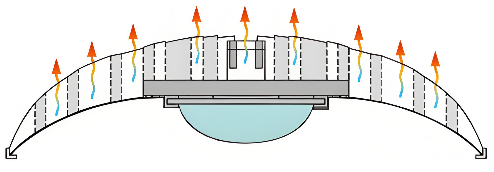
Heat dissipation (radiator → air)
Aluminum profile radiator (anodized is better)
Natural convection or active air cooling combination
The housing needs to be designed with ventilation holes/heat dissipation channels
Recommended heat dissipation area reference table:
Power level Recommended heat dissipation area Heat dissipation method
≤ 5W ≥ 50 cm² Natural convection
5~15W ≥ 120 cm² Natural convection + thermal pad
≥ 20W ≥ 250 cm² Forced air cooling/heat pipe module
Design suggestions:
Avoid heat accumulation in closed structures
Do not stack heating components (such as driver power) under LED modules
NTC thermistor can be embedded to implement over-temperature protection logic
 Thermal Management Basics
- PRODUCTS
- HIGH POWER WHITE
- HIGH POWER COLOR
- COLOR LEDs
- INFRARED LEDs
- UV LEDs
- MINI LEDs
- COB LEDs
- INTEGRATED MOULES
- MARKETS SERVED
- LIGHTING LEDs
- AUTOMOTIVE LEDs
- BIOMEDICAL LEDs
- DISPLAY LEDs
- CURING DISINFECTION LEDs
- PLANT LEDs
- INFRARED SECURITY LEDs
- VISION LEDs
CONTACT US
TEL:+86-0769-81305858
PH:+8613612789419
E-mail:sales@queendomlamp.com